
Key Takeaways
Start here if you want the shortest version of this article.
- ✓ Electrodes must separate excitation (current) and sensing (voltage): hands use the palm for current and the thumb for voltage, feet use the toes for current and the heel for voltage, keeping 1-3cm between them to avoid the current short-circuiting through the skin surface.
- ✓ Electrode size must be sufficient (hands about 2x2cm, feet about 4x4cm) and the material 304 / 316L stainless steel; insufficient foot area causes contact impedance high enough to reach the module compliance-voltage boundary, making readings unstable.
- ✓ Cabling is the main parasitic source for high-frequency impedance: reduce wire count and wire-to-wire coupling first, and finalize conductor spec, plating, and jacket material by measuring target cable samples rather than judging by material names alone.
How accurately body composition measures is largely decided at the hardware design stage. How electrodes are placed, how large their area is, and how cables are routed directly affect contact impedance, parasitic coupling, and high-frequency signal quality - and once these are fixed in the structure and cabling, they are hard to fix after mass production and can only be chased repeatedly. This article starts from the design stage and gives the design essentials for electrodes, structure, and cabling, with the goal of suppressing contact and parasitic problems while you lay out the board, define the structure, and choose the cable. It complements the troubleshooting article: that one covers “how to check after a problem,” this one covers “how to set it so the problem does not happen.”
Scope
This article is a hardware / structural design reference for body composition products built on the BMH05104-2, BMH05108, and BMH05109 modules. The sizes and specs are engineering experience values; module connection should follow the application-circuit and electrical-characteristics chapters of the corresponding module specification and your own complete-product validation. We recommend first understanding BIA four / eight-electrode principles in BIA Body Composition Measurement Principles and Four / Eight-Electrode Selection; for the debugging stage see How to Use Impedance Data to Troubleshoot BIA Body Composition Measurement.
Remember one thing in design: current and voltage must be separated
BIA uses four-electrode (tetrapolar) measurement, whose core is the physical separation of the excitation current electrodes (I) and the voltage sense electrodes (V). All electrodes, routing, and structure in the design must revolve around this: inject current through one pair, sense voltage through a separate independent pair, so that almost no current flows through the sense side and the skin contact impedance is not measured.
Eight electrodes simply apply this four-terminal structure to each limb and then combine segmental paths through switching - the design principle is identical, just with more electrodes and routing and a higher demand for consistency.
Electrode design
Position: current on the outside, voltage on the inside
Electrode position determines the measurement origin and must be fixed and repeatable:
- Hands: the palm contacts the excitation current (HIL / HIR), the thumb contacts the voltage sense (HVL / HVR).
- Feet: the toes contact the excitation current (FIL / FIR), the heel contacts the voltage sense (FVL / FVR).
Put the current electrode at the “far end” and the voltage electrode on the “near, trunk side” so the current passes through the body segment between the voltage sense points first, and what you measure is the true impedance of that segment. Once positions are inconsistent, the origin differs across users and measurements, and results are not repeatable.
Size: large enough to lower contact impedance
- Hand electrodes: recommended about 2cm x 2cm, balancing contact area with grip ergonomics.
- Foot electrodes: recommended about 4cm x 4cm. The sole has a thick callus layer and high natural impedance, so a larger area is needed to lower skin contact impedance.
Too-small foot electrodes exceed the compliance voltage
During measurement, the module needs to drive the body impedance, and its output voltage capability has an upper limit (compliance voltage). If the foot electrode area is insufficient and contact impedance is too high, contact loss consumes the module’s output margin; once it reaches the compliance-voltage boundary, readings become unstable or unmeasurable. Make foot electrodes larger rather than sacrificing area for appearance.
Spacing: keep at least 1-3cm between excitation and sense
Keep 1-3cm of physical spacing between the excitation electrode (I) and the sense electrode (V). Too close, and the current easily “short-circuits” through the skin surface (sweat, dead skin), failing to reach muscle tissue, so what you measure is not the true internal impedance and accuracy drops badly.
Material: 304 / 316L stainless steel
Recommend 304 or 316L stainless steel electrodes for good conductivity and corrosion resistance and stable impedance over long-term use, resisting oxidation that would drift contact impedance.
Cable design: the main parasitic source for high-frequency impedance
Cabling is the most overlooked yet most impactful link for high-frequency measurement in BIA. Parasitic capacitance distorts high-frequency signals, and the classic consequence is “high-frequency impedance instead higher than low-frequency.” Choosing cable to the specs below at the design stage saves much post-production troubleshooting.
- Fewer wires in the bundle: keep only the four electrode wires unless others are necessary, reducing mutual coupling.
- Conductor spec: prefer flexible, stable, low-coupling multi-strand fine wire. Specs such as 49x0.05 or 19x0.08 can be treated as candidate directions, not fixed requirements; finalize only after measuring multi-frequency impedance with target cable samples.
- Core material: tinned copper and silver-plated copper each have engineering advantages in oxidation resistance, solderability, and high-frequency loss, but no single material should be described as universally best; choose by cost, process reliability, and measured impedance results.
- Jacket material: TPE and PU vary widely by formulation in flexibility, dielectric behavior, and abrasion resistance. Do not judge only by the material name; request sample cables from the supplier and measure them.
- Be careful with shielding: in practice, whole-bundle aluminum-foil shielding instead noticeably increases parasitic capacitance and usually needs removing; in theory, shielding each electrode wire individually works better (needs verification). If the bundle contains wires other than the electrode wires, you can shield only those others with foil.
- Routing: for large equipment, route the four electrode wires separately rather than bundled; if bundling is unavoidable, still spread them apart as much as possible.
Design the cable as part of the measurement circuit
Do not casually attach any wire after the PCBA is tuned. The cable’s parasitic capacitance enters the measurement result directly, especially in a high-frequency band like 100kHz. The cable spec should be validated with the module at the prototype stage: with the target cable connected, measure multi-frequency impedance, confirm high frequency is below low frequency and both simulated and body impedance are normal, then finalize the production cable. Customers can also send candidate cable samples to us for evaluation; we can support checks with professional instruments, and if cable sourcing support is needed, we can help connect with our partner cable manufacturers.
Design in testability
A little extra thought at design time pays off in later debugging and mass-production calibration:
- Electrode contact pressure / support: ensure stable electrode contact under normal use posture, avoiding foot pads or limit stops interfering with contact or weighing.
- Separate excitation / sense layout: keep the current path and the voltage sense path as separate as possible on the PCB and routing to reduce coupling.
- Reserve a way to connect a simulated human-impedance model board: prototypes and production lines can connect the model board to the complete product’s electrode terminals to quickly validate the PCBA, cable, and electrode path, separating “machine path” problems from “human contact” problems.
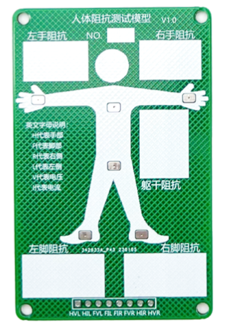
The image above shows a simulated human-impedance model board example. Customers can connect the model board to the complete product’s electrode terminals for path validation during prototype debugging or production-line checks.
Extra design points for eight electrodes
Eight electrodes have more electrodes and segmental switching; pay extra attention in design:
- Left-right consistency: keep the electrode size, position, and cable spec of the left and right arms and legs as consistent as possible, otherwise the left-right segmental impedance shows non-physiological differences.
- Sensitive trunk path: the trunk impedance is only about twenty-some ohms and is extremely sensitive to electrode position and routing; optimize the placement of the related electrodes and cabling.
Design self-check list
Run through before finalizing:
- Are electrodes current / voltage separated, with fixed positions (palm/thumb, toes/heel)?
- Is electrode size sufficient (hands about 2x2cm, feet about 4x4cm), and do the feet lower contact impedance enough?
- Is the excitation-to-sense spacing >= 1-3cm? Is the material 304 / 316L stainless steel?
- Are module power, reference ground, electrode interfaces, and recommended peripheral circuits connected according to the specification, without modifying the excitation path?
- Does the cable reduce wire count and coupling, and has the target cable sample been used to validate conductor spec, plating, jacket material, and shielding method?
- Have you validated multi-frequency impedance (high < low) with the target cable at the prototype stage?
- Have you reserved a way to connect a simulated human-impedance model board for prototype and production-line validation of the PCBA, cable, and electrode path?
- (Eight-electrode) Is it left-right symmetric and is the trunk path optimized?
FAQ
Must electrodes be stainless steel? Can gold-plated / conductive rubber work?
The key is stable conductivity, corrosion resistance, and no long-term contact-impedance drift. 304 / 316L stainless steel is an economical and stable conventional choice; other materials must self-validate long-term contact-impedance stability and corrosion resistance, not just initial conductivity.
Can foot electrodes be made smaller for better appearance?
Not recommended. Sole callus impedance is high, and too-small electrodes consume the module’s output margin, causing unstable or no readings. When appearance conflicts with measurement stability, prioritize electrode area.
Why can’t I wrap the electrode wires in whole-bundle aluminum-foil shielding?
In practice, whole-bundle foil shielding noticeably increases parasitic capacitance to ground, worsening high-frequency measurement (high frequency above low frequency). If shielding is needed, prefer separate routing, individual shielding, or shielding non-electrode wires, and validate by measurement.
Once the cable spec is set, does it still need validation?
Yes. Cable parasitics only appear when the target cable is connected and multi-frequency and body impedance are measured. Be sure to validate at the prototype stage with the final cable (high-frequency impedance below low-frequency, both simulated and body impedance normal) before mass production, to avoid batch rework afterward.
Previous
Body Composition Algorithm Selection and Integration Guide
Next
How to Validate Body Composition Accuracy - A DEXA Comparison Methodology
Related Articles
Continue with articles covering adjacent engineering topics and implementation details.
Engineering Debugging
How to Use Impedance Data to Troubleshoot BIA Body Composition Measurement
A BIA measurement debugging guide for the BMH05104-2 / BMH05108 / BMH05109 body composition modules, covering why to go back to raw impedance data, normal impedance magnitudes (the eight-electrode body model), a check order of stability then frequency relationship then segmental symmetry, and how to locate common faults in electrode contact, cable parasitic coupling, broken wires, and measurement posture.
June 15, 2026
Body Composition Principles
BIA Body Composition Measurement Principles and Four / Eight-Electrode Selection
Starting from the conductivity principle, this guide explains how BIA measures body composition, what the resistance and reactance inside impedance represent, why a four-electrode setup is required instead of two, and the difference between single and multiple frequencies. It then compares four-electrode (two-leg / two-arm) and eight-electrode (segmental) approaches by measurement path, output items, accuracy, cost, and product form, to help you pick the right approach and module for scales, wearables, and professional analyzers.
June 15, 2026
Solution Evaluation
Body Composition Module Quick Selection - Product Fit, Accuracy Difference, and Integration
For product managers, buyers and engineering teams new to the BestHealth body composition solution, this article first answers four first-pass questions: which modules are available, what product each fits, how much accuracy differs between four-electrode and eight-electrode solutions, and how to integrate the module into the finished device. It then compares BMH05104-2, BMH05108 and BMH05109, and explains what makes a strong body composition solution: a self-designed BIA measurement front end, validation data, certification support, SDK/API completeness, structural design support and response speed.
June 26, 2026
BestHealth
Need technical support for your next project?
Share your application scenario and target requirements. Our team can help with device selection and solution planning.